
The Load Cell Amplifier is a precision amplifier with In-Built Reference Voltage Source for interfacing with the Strain Gauge Bridge type Load Cells.
The unit provides a highly stable temperature compensated 10V reference voltage source for excitation of the Load Cell. The differential milliVolt (mV) output of the Load Cell is Amplified and Filtered by the unit to provide isolated 0-10V or 4-20mA output linearly proportional to the Load Cell mV signal.
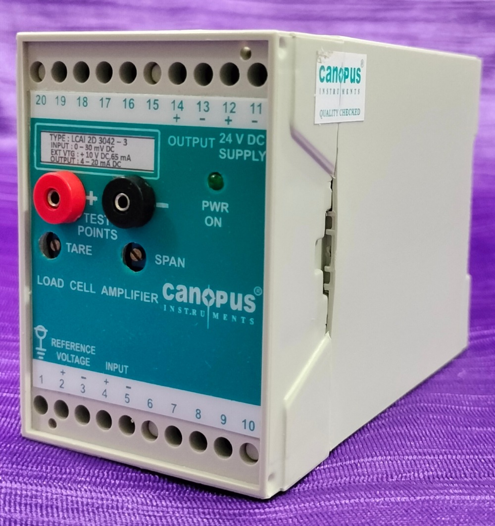
Provision for TARE adjustment is useful in setting 0V (or 4mA) output for No-load condition to compensate for the Dead Weight of the system.
These amplifier units are extremely stable and accurate for long term measurement applications and can also be calibrated to suit the Load Cell response characteristics so that maximum sensitivity is available in the measurement range.
Features
Applications
Technical Specification
| Input Differential I/P signal from Loadcell | Range(mVDC)0-10, 0-16, 0-20,0-30,0-250, or Customized I/P range mVDC | Factory Set |
| Full Scale O/P Calibration Range. | 50% to 100% of I/P range | |
| Input Resistance | 1M Ohms | |
| TARE Adjustment Range | ±30% of I/P range | |
| Reference Voltage | +10VDC, 60mA Max. | |
| Accuracy | ±0.01% | |
| Load Regulation | <0.02% | |
| Temp. coefficient | <10ppm | |
| Output Range | For Voltage | 0-10VDC |
| For Current | 4-20mADC | |
| Load Resistance | For Voltage | >1 kOhm |
| For Current | < 500 Ohm | |
| Performance | Accuracy | ±0.2% of Span |
| Non –Linearity | 0.1% | |
| Temp. Drift | <0.01% / °C | |
| Calibration | Tare & Span (Trimpot) | |
| Response Time | 50 Milliseconds* |
Mechanical Specification
| Pin | Details | Pin | Details |
|---|---|---|---|
| 1 | Shield | 11 | GND |
| 2 | + Reference to Load Cell | 12 | +24VDC |
| 3 | – Reference to Load Cell | 13 | -Output |
| 4 | +Input From Load Cell | 14 | +Output |
| 5 | -Input From Load Cell | 15 | NC |
| 6 | S1(Response Time Setting) | 16 | NC |
| 7 | S2(Response Time Setting) | 17 | NC |
| 8 | S3(Response Time Setting) | 18 | NC |
| 9 | S4(Response Time Setting) | 19 | NC |
| 10 | C(Response Time Setting) | 20 | NC |
Single input & Single output Converter
